How To Fix Sienna Sliding Door Rattles
My 2004 Toyota Sienna's door would not open or shut when I used the remote or the inside buttons. It would only work when I pulled the handle. Hither is a breakdown of the symptoms I was having with my 2004 Toyota Sienna XLE:
- The right sliding door would not open up or close if I used the keychain remote (you could hear information technology try but the door wouldn't e'er unlatch)
- The right sliding door would not open or shut if I used the button on the ceiling betwixt the driver and rider's seat or the push button on the door post in front of the door (information technology would be obvious that information technology was trying to open and would movement a millimeter or so just that'southward information technology)
- The correct sliding door would operate correctly if you physically pulled the outside or inside handles
- The slide door lock release motor was getting 12 volts when I tried to remotely open the door
All of this is pointing to the motor inside the door that essentially "pulls the handle" for you when yous remotely open up the door. Hither's a video of me demonstrating the problem:
How to Set up 2004-2010 Toyota Sienna Sliding Door Volition Not Open or Close With The Remote-How to Supercede the Slide Door Lock Release Motor Assy
Hardware/Parts Needed:
- 2004-2010 Toyota Sienna XLE with at least one power sliding side door
- Right (Rider-side Sliding Door): Motor Assembly, Slide Door Lock Release Control (RH) – 85620-08061
- Left (Commuter's-side Sliding Door): Motor Assembly, Slide Door Lock Release Command (RH) – 85620-08071
- Replacement Motor (Only if you want to fix your part, not replace information technology, see a video on this repair hither)
I didn't replace the motor merely if you don't want to spend the coin on the replacement part you can just replace the part of it that went bad, the motor. I don't cover the motor replacement in this article. - Important: Order ii replacement screws (only one comes in each package): Spiral, door within handle – 69296-08030 (because the screws that hold the motor assembly on the door had LockTite on them when they were installed and are almost impossible to remove and the heads strip out hands–I've been advised that Toyota techs only cut the heads of them off to remove this part)
- Plastic door panel retainer clips
(because some of them will often shatter when yous pop off the door panel)
Tools Needed:
Important Note: I'm borrowing some of these images from another repair I did on my van:
How to Replace the Power Sliding Door Cables on a 2004-2010 Toyota Sienna
Therefore, some of these pictures will be from the left door and some of them will exist from the right door. The 2 doors are but mirror images of ane another though. If the cables on your door fray or the door gets stuck half style open come back to the link higher up to read how you lot can practise that repair yourself.
A Word of Encouragement
If you are wondering if you tin practice this repair, delight check some of these comments I've received from readers who used this guide to prepare their Sienna:
This guide was the best written machine repair that I've e'er seen. Showing me how to take everything apart step by step, how to troubleshoot the motor to make sure I was fixing the right affair, plus all of the tips and tricks for how to avoid dropping the bolts into the window were fantastic. Not to mention embedded links in the guide to have me directly to the correct parts to guild from Toyota. Give thanks yous for putting this much time and effort into sharing your cognition. You saved me hours of frustration and hundreds of dollars. –Frank P.
Give thanks you for an awesome guide. I tinker with repairs all the fourth dimension in a quest to salvage coin, and this might take been the clearest guide I've ever used to do a repair. Those coming here wondering if they tin can do this: Have no fearfulness! –Justin
Thank you so much for this posting! Excellent write upwardly and pictures. You saved me hours of frustration and hundreds of dollars! I just changed both sliding door lock mechanisms on my Sienna. Starting time door took me a few hours considering of the screws that held in the door lock motor were stubborn. Ended up using your dremel trick. My 2d door went smoothly, only took me an 60 minutes or then. Thx again. –Matt
Repair Outline
Click on the links to leap down to the steps:
- Footstep 1: Remove the "Slide Door Window Garnish."
- Step two: Remove the "Side Trim Board Comprehend."
- Step three: Remove the Rear (side) Door Trim Board Sub-Assembly.
- Step iv: Locate the slide door lock release motor associates.
- Step 5: Troubleshooting the slide door lock release motor associates.
- Step half-dozen: Unbolt the window.
- Stride 7: Tape the window up and out of your way.
- Step eight: Remove the bolts from the blackness internal admission panel (technically called the "zipper panel").
- Step 9: Disconnect the electrical connector and cable from the van door.
- Stride 10: Disconnect the control rod from the slide door lock motor.
- Step 11: Remove the 2 slide door lock release motor assembly screws.
- Footstep 12: Reinstall the 2 phillips-head screws into the new door lock release motor associates.
- Step 13: Reconnect the control rod.
- Step xiv: Reconnect the wiring connector to the door lock release motor associates.
- Step 15: Reattach the electrical connector and cablevision at the top of the access panel.
- Step 16: Reinstall the the bolts into the metal access console.
- Step 17: Reinstall the ii window bolts.
- Stride 18: Examination the repair.
- Step nineteen: Reinstall the interior trim of the sliding door.
- Step 20: Reinstall the "Side Trim Board Cover."
- Step 21: Reinstall the "Slide Door Window Garnish."
- Step 22: Y'all're Finished
Repair Steps
Footstep 1: Remove the "Slide Door Window Garnish."
This is the black plastic piece that wraps the lower rear corner of the window opening. If you are looking at the shop manual picture below it is a scrap misleading because the epitome shown is the view from the outside with the window removed and in your situation the window will completely cover it up. If you don't remove this corner slice you cannot remove the plastic cover from the inside of the door. Lower the window as far downwardly as information technology will get and pry out the center of the plastic plug in the middle of the clip and so the entire clip will come out–brand sure not to lose the center of the prune.
| |
| Slide door window garnish as seen in the shop transmission (shown every bit the left door view) |
| A wide angle view of the slide door window garnish, circled in scarlet: |
| Left Door: Location of the slide door window garnish |
This slice is held in place by a 2-piece plug. Outset utilize a thin flat screwdriver to elevator out the center of the plug as seen below:
| |
| Left Door: Slide door window garnish plug unsnapped |
One time you take popped out the heart of the plug as seen higher up then you can take a flat head screwdriver and pull the plug completely out. Here's what the plug looks like when you take it out:
| |
| Slide door window garnish plug removed |
Once yous have the plug removed y'all can pull off the window garnish by getting your fingers under the inside edge and pulling towards the window opening as seen below:
| |
| Left Door: Removing the slide door window garnish |
1 thing to note is that in that location are 2 metallic clips that are supposed to stay on the plastic window garnish but may remain on the door or fall off. Place the clips back on the garnish as seen beneath:
| |
| Clip location on the slide door window garnish |
One of the clips remained on the door every bit seen here:
| |
| Left Door: This clip stayed on the door |
Put the clips back on the plastic trim correct away so you don't loose them but make sure the tab is oriented on the right side (one side is meant to be clipped on the plastic and 1 side is made to be clipped on the metal door body) like this:
| |
| Clip orientation |
Step 2: Remove the "Side Trim Board Cover."
This is the plastic slice that surrounds the inside door handle as seen in the diagram beneath:
| |
| Side trim board cover (i.e. the plastic that goes around the within door handle and window switch) |
There are 2 screws on the front edge of the door so youMUST exist able to get the door open to remove information technology. At first I was not able to get my door opened but past playing around with pulling the handle on the inside while pushing out on the door (forepart and back of door) I was able to get information technology to open.
| |
| Left Door: Spiral locations on the side trim lath cover |
Once you've removed the 2 screws you tin pop the cover off past pulling toward the inside of the vehicle at the location shown below (left door):
Of import: Don't pull this plastic embrace away from the door forcefully. The window switch is retained by the electrical wiring. Only remove the switch from the encompass past removing the 2 phillips caput screws. Reinstall the screws into the trim lath cover so you tin can keep rail of them. You need the switch afterward in the repair considering you cannot operate the window without the slide door'south switch installed (not fifty-fifty by using the driver's door switch). Here are the switch screw locations:
| |
| Left Door: Remove the two screws from the window switch |
Annotation:At some indicate you lot will either want to disconnect the positive battery terminal from your battery or simply put the sliding doors in manual style so you tin can manually open and shut your sliding door as needed to complete the repair. The push to put the sliding doors in manual mode is located at the left articulatio genus of the driver:
| |
| Sliding door manual button (in transmission manner–pushed in) |
Footstep 3: Remove the Rear (side) Door Trim Board Sub-Associates.
This is the main plastic console on the within of the door:
| |
| Left Door: The side door trim board sub-associates and the one screw on the lower edge toward the rear of the van |
Important: in that location is one phillips/hex-head screw at the very bottom rear corner of the trim that must be removed earlier prying the trim lose. Information technology has a 8-mm nut caput on it. I advise using a socket to remove it. I first tried using my trusty brusk phillips screw driver simply I wasn't able to put enough strength onto the tip to become information technology to budge. I'd use a socket and ratchet if I were you.
| |
| Right Door: The single screw on the side door panel located on the lower rear edge, as seen from floor level with the door open |
Here is the diagram of the clips (indicated past dotted triangles):
| |
| Left Door: Side door trim lath sub-assembly clip diagram (note: this diagram is for the left door) |
The kickoff time I did this repair I wrapped a large flat screwdriver with electric tape and used it to pry up the console, working my way around the edge. Once all ix clips are freed then you will elevator upward the panel and it will lift upwardly and out (it "hangs" from the tiptop).Notation: if your van has the born window shades you don't need to mess with them, they come up off with the plastic assembly, all in one slice. You tin can as well pop the inner door panel gratis past pulling on the cup holder similar I did the second time I did this repair as seen below:
| |
| Correct Door: Popping the console free by pulling on the cup holder |
Then I pulled here on the front border of the inner door panel:
| |
| Left door: Popping gratis the rear border of the interior console |
Here's the panel removed:
| |
| Right door: interior panel removed |
Step 4: Locate the slide door lock release motor associates.
It is located below and toward the rear of the vehicle from the inside door handle and is circled in ruby below:
| |
| Right door: Location of the slide door lock release motor assembly |
| |
| Right door: diagram and location of door lock release motor associates |
Step five: Troubleshooting the slide door lock release motor assembly.
Hither I am activating the door latch with the keychain remote:
At this point I wanted to know that the motor was getting power. And so I disconnected the connector and hooked my multimeter up to the van side of the connector and pressed the remote push. It was getting 12 volts simply fine. Hither is a video of me testing it:
So, because the motor was getting ability I determined that the motor was bad. I then looked for where you unbolt the motor assembly and was a flake surprised that the heads of the screws are on the dorsum side (within the door)! Ugh. Come on Toyota Engineers–don't you retrieve of the repair guy ever?!?! Here is a picture of the two bolt ends poking through the outside of the role:
| |
| Bolt Locations (these are the ends sticking out on the side nosotros tin easily become to) |
So nosotros are going to need to unbolt the panel that holds all the door and window controls. The problem is that the window is continued to this console. If you don't unbolt the window y'all'll be lifting upward the unabridged window with this panel and could damage it. I didn't want to comletely remove the entire window, because that is actually overkill for this repair then I opted to go another route–simply unbolting the window and and then taping it in the up position and out of the way. Hither'due south how I did it…
Step 6: Unbolt the window.
Remove the two plastic plugs that embrace the access holes. Y'all can pull them out with your fingers:
| |
| Right Door: Window bolt access pigsty plug locations |
| |
| Window admission pigsty plugs removed |
At present adjust the window height then you accept the window bolts centered on the holes:
| |
| You can line up the window bolts with the holes for much easier removal |
If you disconnected the window switch then y'all'll need to re-fastened it to the wiring so you lot tin can roll the window down. I tried rolling downwards the window with the driver'south door switch just the window will non operate without the door's switch installed:
| |
| Power window switch |
Caution: Exist careful not to driblet the bolts downwardly into the door when you lot are removing them!!When I did this latest repair I came upwardly with a trick to help keep from dropping the bolts downwards into the door. The flim-flam is to put some tape upwardly over the edge of your socket and so that the socket hole is smaller and the head of the bolt fits tightly into the socket:
| |
| Put record up and over the edge of your socket to retain the bolt when it is loose |
With the tape on the socket yous'll need to push harder to get the socket to fit over the bolt, but this is adept:
| |
| 10mm socket on one of the two window bolts |
The tape worked slap-up to retain the bolt in one case it was loose:
| |
| The trick worked nicely |
Stride 7: Tape the window upward and out of your mode.
Once you have removed the ii bolts you can carefully elevator the window upwards (with the door open reach ane manus inside and i outside) and I used packing tape to tape information technology all the fashion upward at the top:
| |
| A single piece of packing tape held the window upwardly nicely |
Step 8: Remove the bolts from the blackness internal admission panel (technically called the "attachment panel").
This volition give you access then yous can unbolt the slide door lock release motor assembly. When I went to exercise this on my right door at that place were only seven bolts, 2 of which were connected to grounds. DO NOT remove any of the bolts on the inside of the pan, just the ones effectually the edge equally seen in the diagram:
| |
| Bolt locations of the internal access panel–note this is for the left door |
In real life, circled in red are the 9 bolts you must remove:
| |
| Left Door: 9 bolt locations on the internal access panel |
My door was missing some of those bolts, I think I had 7 this last time I tore into this door 🙂 On the right door, which had basis wires attached to bolts, I taped the grounds in place and then that I would remember to re-connect them:
| |
| I of the grounds taped in place (because I accept bad memory) |
Take note that the ground bolts are longer:
| |
| The ground bolts |
You may need to pry the console abroad from the door if this is the offset time yous've removed it because there is a cream gasket that makes it stick to the door. Even the time I had to pry it away I was able to do information technology with my fingers. Y'all are not going to movement the panel far from the door because it will still exist attached to various other cables.
Pace 9: Disconnect the electric connector and cable from the van door.
To make information technology easier to open this panel and get behind it to unbolt the motor assembly y'all should unclip the electrical connector from the van (don't disconnect the ii ends of the electrical connector, simply slide the whole thing frontwards to release information technology from where information technology is locked into place on the door) and release the black cable from its retaining prune at the top of the black panel:
| |
| Release the electrical connector from the van and release the cable from its clip to give yourself room |
This is what it will await like with the electrical connector released:
| |
| Here they both are released |
Stride 10: Disconnect the control rod from the slide door lock motor.
First locate the blue connector snap and rotate it counter clockwise to unsnap it from the motor:
| |
| Button down as shown to unsnap the plastic retainer from the connector rod |
Then it will look like this:
| |
| The bluish plastic piece has been rotated counter-clockwise and unsnapped from the rod |
Pull the rod direct out of the blue plastic slice to release the motor from the control rod:
| |
| Here the control arm has been disconnected from the motor assembly |
Footstep 11: Remove the ii slide door lock release motor assembly screws.
Tip: These screws were near incommunicable for me to remove equally you can read beneath. One reader, Justin, generously shared a tip in the comments that I would like to insert here, which may brand this step much easier for y'all: Apply a heat gun to heat upward the screw (and loctite on the threads) and the screw volition easily come out. If that doesn't work for you lot, follow forth below, only if it does, and your screws come up right out, skip down to Pace 12.
Some other reader, Jed, commented that these are JIS-headed screws, "Japanese Industry Standards" and having the right screwdriver may assistance in their removal. I don't ain one of these screwdrivers but you can buy them here.
Looking down from the top here are where they are located, on either side of the round indention in the black metal admission console:
| |
| Right Door: The ii screws holding the slide door lock release motor assembly onto the access panel |
You can try to unscrew these but I was non able to. Subsequently this repair I contacted my Metro-Toyota.com contact and he asked his techs and they advised him that they just cut the heads off the crews to remove this function. And then I wouldn't sweat this too much, I'd accept your Dremel Tool and but grind the head off of each i. I had to learn a harder style and this is what I did… Showtime the phillips caput stripped on me then I cut a flat slot in the heads with my Dremel Tool
:
| |
| Here I have used a cut deejay on my Dremel tool to make a slot for a apartment-caput screw driver |
Even afterwards cutting a slot in the caput they notwithstanding would non come out, because the nut stop turned with the commodities that is imbedded in the plastic. I tried to hold the other cease still, first with a vice grip, then with a flat spiral commuter, and then with a chisel:
| |
| Right: I used my Dremel to flatten i side and then wedged a screw driver in there to endeavour to hold information technology all the same, to no avail |
And so afterwards failing to be able to concord the other ends still with a vice grip and a chisel, I took my Dremel tool to the other side equally well:
| |
| Right Door: The left side "nut" end ground off smooth |
| |
| Correct Door: The right side "nut" stop ground off smooth |
Finally, after that I was able to remove both screws and the door lock release motor assembly came free:
| |
| Right Door: Slide door lock release motor assembly removed, finally! |
Footstep 12: Reinstall the ii phillips-head screws into the new door lock release motor assembly.
The new assembly will not come with parts so if you lot had to destroy the erstwhile screws like I did, brand sure y'all club them (or club them in advance but in case if yous didn't remove the part before ordering parts).
| |
| The two new screws inserted into their holes |
I started them by hand to make sure I didn't cross thread them. My stubby screw driver came in real handy at this point since in that location's not room for a normal length spiral driver:
| |
| It helps a lot to have the right tools and my stubby phillips-head screw driver comes in handy on this step |
Pace 13: Reconnect the command rod.
The new part comes with the control rod and then you can use the old one or the new ane. I used the new 1. Insert the end of the rod into the blue plastic piece. This is what you should accept:
| |
| Insert the end of the new control rod into the pinkish plastic slice similar this |
Now rotate the pink plastic piece in a clockwise rotation to snap it on to the horizontal part of the rod. If you cannot rotate it around then pull the rod out, re-locate the blue plastic piece and so effort again. This is what it volition look like when it is properly locked in place:
| |
| Rotate the pink plastic piece clockwise |
| |
| Snap the pinkish plastic piece downward onto the rod |
Step fourteen: Reconnect the wiring connector to the door lock release motor associates.
| |
| Reconnecting the wiring connector |
The connector should snap into place:
| |
| Right Door: Reconnect the slide door lock release motor assembly wiring connector |
Step 15: Reattach the electrical connector and cablevision at the top of the access panel.
The electrical connector just slides on towards the rear of the van.
| |
| Don't forget to put both of these dorsum in identify |
Footstep 16: Reinstall the the bolts into the metal access panel.
| |
| Diagram of the attachment console |
Step 17: Reinstall the 2 window bolts.
Use my electrical tape flim-flam I shared in Step half-dozen then you don't drop the bolts down into the window. Yous may want to add another layer of tape if the bolts don't fit tightly. Don't forget to reinstall the two safe plugs after tightening them upwardly.
Pace 18: Exam the repair.
At this point you should exist able to test the door past pressing the button on the remote or any of the other buttons on the van. Brand sure the power sliding doors are enabled by the drivers's left knee on the dash (the push should be popped out and the orange should show). Here is a video of mine after the repair:
One thing to note about the video above is that unremarkably the motor would have to release the latch right earlier the door shuts (as well as right before it closes) but for some reason Toyota has designed this door so that the door does not lock in the open position when the window is down and I had the window downward when I shot this video (I'd forgotten well-nigh that).
Step xix: Reinstall the interior trim of the sliding door.
Earlier you go to put it on make sure all the clips are in place and not broken. In that location are 10 of them and as you can see from the image below, I have had to replace the bottom two (the blue ones). You will nigh always break some of the plastic clips that hold the trim in place so I ordered a bag of them from amazon (link for a purse of 25 of them here). A give-and-take almost snapping them all in place: if yous don't have them snapped all they way in they may not line up with the pigsty they are supposed to snap into so brand certain none of them are out of identify.
| |
| Location of the 10 clips on the back side of the sliding door panel |
Brand sure at that place are no clips withal stuck into the metallic trunk of the sliding door of the van:
| |
| Use a screwdriver to remove any clips that did non come out with the door panel |
I ordered a package of 25 of these retainer clips from amazon.com, which I used in both repairs.
| |
| 25 clips for $8 at amazon.com |
Hang the top of the interior trim on the tiptop edge of the door–it should fit snug against the window. Look along the edge of the trim to see that the snaps are lining upwards with their holes so start snapping the trim on the metal door frame.
| |
| Line the snaps up with the holes earlier pressing (or banging) on the door console to snap back together |
Finally, don't forget to reinstall that one sneaky 8mm head screw at the bottom rear of the door:
| |
| Left Door: Reinstalling the lower screw |
Footstep xx: Reinstall the "Side Trim Board Encompass."
Reinstall the window switch screws.
| |
| Reinstall the ii window switch screws |
Snap the trim board dorsum into identify:
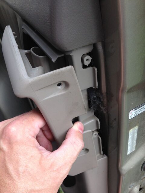
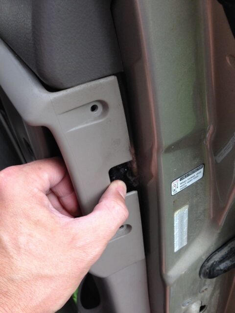
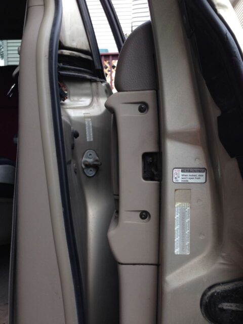
Reinstall the two screws on the edge of the trim lath as seen below:
Step 21: Reinstall the "Slide Door Window Garnish."
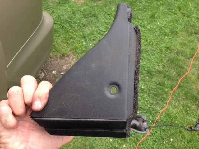
Brand sure that both clips are in place before snapping it in (they could take stayed on the body of the van when you removed it):
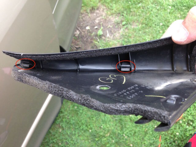
Align the piece with the pigsty and snap the plastic clip back in place:
| |
| The window garnish reinstalled |
Step 22: You're Finished!
Now you've saved yourself hundreds of dollars! Skillful work. Delight let me know in the comments if you have questions or if you'd be kind enough to share with everyone that you lot were able to complete this repair–information technology is encouraging for others to hear you did it yourself also!
Amazon Acquaintance Disclosure: Every bit an Amazon Associate I earn from qualifying purchases. This means if you click on an affiliate link and purchase the detail, I will receive an chapter commission. The price of the item is the same whether information technology is an affiliate link or not. Regardless, I only recommend products or services I believe volition add together value to Share Your Repair readers. By using the chapter links, you lot are helping support Share Your Repair, and I genuinely appreciate your back up.
How To Fix Sienna Sliding Door Rattles,
Source: http://www.shareyourrepair.com/2015/05/2004-2010-toyota-sienna-slide-door-lock-release-motor-assy-replacement.html
Posted by: holimansque1965.blogspot.com


0 Response to "How To Fix Sienna Sliding Door Rattles"
Post a Comment